简介
spinal.lib.misc.pipeline 提供了一套流水线API。相对于手动流水线它的主要优点是:
无需预先一次性定义好整个流水系统中所需的所有信号元素。您可以根据设计需要,以更灵活的方式创建和使用可分级的信号,而无需重构所有中间阶段来适配该信号。
流水线的信号可以利用SpinalHDL的强大参数化能力,并且如果设计构建中不需要特定的参数化特征,则可以进行优化/移除,而不需要以显著的方式修改流水系统设计或项目代码库。
手动重定时要容易得多,因为您不需要手动处理寄存器与仲裁逻辑。
它会自行管理仲裁器
API由4个主要部分组成:
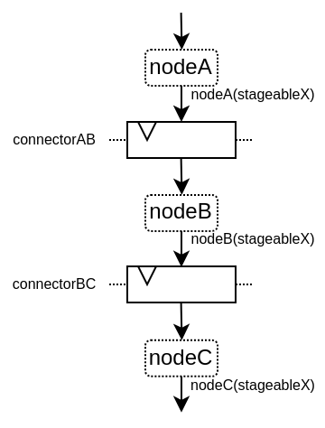
Node(节点):表示管道中的层Link(链接):允许节点相互连接Builder(构建器):生成整个管道所需的硬件Payload(负载):用于获取流水线的节点上的硬件信号
需要注意的是,Payload 不是硬件数据/信号实例,而是在流水线各节点检索数据/信号的键。流水线构建器会据此自动完成所有节点间同一 Payload 实例的互连 / 流水线化处理。
以下是一个用于阐述的例子:
以下是关于此API的视频:
简单示例
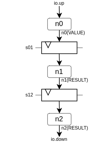
下面是一个简单的例子,它只使用了基本的API:
import spinal.core._
import spinal.core.sim._
import spinal.lib._
import spinal.lib.misc.pipeline._

class TopLevel extends Component {
  val io = new Bundle {
    val up = slave Stream (UInt(16 bits))
    val down = master Stream (UInt(16 bits))
  }

  // Let's define 3 Nodes for our pipeline
  val n0, n1, n2 = Node()

  // Let's connect those nodes by using simples registers
  val s01 = StageLink(n0, n1)
  val s12 = StageLink(n1, n2)

  // Let's define a few Payload things that can go through the pipeline
  val VALUE = Payload(UInt(16 bits))
  val RESULT = Payload(UInt(16 bits))

  // Let's bind io.up to n0
  io.up.ready := n0.ready
  n0.valid := io.up.valid
  n0(VALUE) := io.up.payload

  // Let's do some processing on n1
  n1(RESULT) := n1(VALUE) + 0x1200

  // Let's bind n2 to io.down
  n2.ready := io.down.ready
  io.down.valid := n2.valid
  io.down.payload := n2(RESULT)

  // Let's ask the builder to generate all the required hardware
  Builder(s01, s12)
}
这将产生以下硬件:
下面是一个仿真波形:
下面是相同的示例,但使用了更多的API:
import spinal.core._
import spinal.core.sim._
import spinal.lib._
import spinal.lib.misc.pipeline._

class TopLevel extends Component {
  val VALUE = Payload(UInt(16 bits))

  val io = new Bundle {
    val up = slave Stream(VALUE)  // VALUE can also be used as a HardType
    val down = master Stream(VALUE)
  }

  // NodesBuilder will be used to register all the nodes created, connect them via stages and
  // generate the hardware.
  val builder = new NodesBuilder()

  // Let's define a Node which connect from io.up .
  val n0 = new builder.Node {
    arbitrateFrom(io.up)
    VALUE := io.up.payload
  }

  // Let's define a Node which do some processing.
  val n1 = new builder.Node {
    val RESULT = insert(VALUE + 0x1200)
  }

  //  Let's define a Node which connect to io.down.
  val n2 = new builder.Node {
    arbitrateTo(io.down)
    io.down.payload := n1.RESULT
  }

  // Let's connect those nodes by using registers stages and generate the related hardware.
  builder.genStagedPipeline()
}
Payload
Payload 对象指向可以通过流水线传输的数据。从技术上讲,Payload 是一个具备名称属性的 HardType 它被用作在流水线特定阶段中检索信号的“键”。
val PC = Payload(UInt(32 bits))
val PC_PLUS_4 = Payload(UInt(32 bits))

val n0, n1 = Node()
val s01 = StageLink(n0, n1)

n0(PC) := 0x42
n1(PC_PLUS_4) := n1(PC) + 4
请注意,我习惯于使用大写对 Payload 实例命名。这是为了明确,这不是一个硬件信号,而更像是一个“键/类型”的访问标识。
Node
Node 主要托管有效/就绪仲裁信号,以及所有流经该节点的 Payload 所需的硬件信号。
您可以通过以下方式访问其仲裁器:
API |
访问 |
描述 |
|---|---|---|
|
RW |
指定节点上是否存在事务,由上游逻辑驱动。一旦置为1,仅可在以下两种情况发生后的下一个时钟周期撤销置位: |
|
RW |
表示节点中的事务是否可以向下游传递,由下游驱动以创建反压。当没有事务( |
|
RW |
指定节点的事务是否正在从流水线中取消,由下游驱动。当没有事务时( |
|
RO |
|
|
RO |
|
|
RO |
|
|
RO |
当节点事务成功继续传递时为 |
|
RO |
当节点事务将不再存在于节点上时(从下一周期开始)为 |
|
RO |
当节点事务正在被取消时为 |
请注意, node.valid/node.ready 信号遵循与 Stream 中相同的规范。
Node 的控制信号( valid/ready/cancel )和状态信号( isValid 、 isReady 、 isCancel 、 isFiring 等)是按需创建的。例如,若从不引用 ready 信号,即可创建无反压的流水线。这也是为何读取状态时应使用状态信号,而驱动操作时仅使用控制信号,这一点至关重要。
以下是节点上可能出现的仲裁情况列表。valid/ready/cancel 定义了我们所处的状态,而 isFiring/isMoving 是这些状态的结果:
valid |
ready |
cancel |
描述 |
isFiring |
isMoving |
|---|---|---|---|---|---|
0 |
X |
X |
无事务 |
0 |
0 |
1 |
1 |
0 |
正在进行 |
1 |
1 |
1 |
0 |
0 |
阻塞 |
0 |
0 |
1 |
X |
1 |
取消 |
0 |
1 |
请注意,如果您想要建模诸如CPU级可能的阻塞和刷新的情况,可以查看 CtrlLink,因为它提供了执行此类操作的 API。
您可以通过以下方式访问由Payload引用的信号:
API |
描述 |
|---|---|
|
返回对应的硬件信号 |
|
与上述相同,但包括一个用作“次要键”的第二个参数。这有助于构建多通道硬件。例如,当您有一个多发射CPU流水线时,您可以使用通道Int id作为次要键 |
|
返回一个新的Payload实例,该实例连接到给定的Data硬件信号 |
val n0, n1 = Node()

val PC = Payload(UInt(32 bits))
n0(PC) := 0x42
n0(PC, "true") := 0x42
n0(PC, 0x666) := 0xEE
val SOMETHING = n0.insert(myHardwareSignal) // This create a new Payload
when(n1(SOMETHING) === 0xFFAA){ ... }
您不仅可以手动方式来驱动/读取流水线的第一/最后一级的仲裁信号/数据,也有一些实用工具可以连接这些边界上的级。
API |
描述 |
|---|---|
|
由反压流驱动节点仲裁。 |
|
由数据流驱动节点仲裁。 |
|
由节点驱动反压流仲裁。 |
|
由节点驱动数据流仲裁。 |
|
由反压流驱动节点。提供的lambda函数可以用于连接数据 |
|
与上述类似,但适用于 |
|
由节点驱动反压流。提供的lambda函数可以用于连接数据 |
|
与上述类似,但适用于 |
val n0, n1, n2 = Node()

val IN = Payload(UInt(16 bits))
val OUT = Payload(UInt(16 bits))

n1(OUT) := n1(IN) + 0x42

// Define the input / output stream that will be later connected to the pipeline
val up = slave Stream(UInt(16 bits))
val down = master Stream(UInt(16 bits)) // Note master Stream(OUT) is good as well

n0.driveFrom(up)((self, payload) => self(IN) := payload)
n2.driveTo(down)((payload, self) => payload := self(OUT))
为了减少冗长,在 Payload 与其数据表示之间有一组隐式转换,可在 Node 下使用:
val VALUE = Payload(UInt(16 bits))
val n1 = new Node {
    // VALUE is implicitly converted into its n1(VALUE) representation
    val PLUS_ONE = insert(VALUE + 1)
}
您还可以通过导入它们来使用这些隐式转换:
val VALUE = Payload(UInt(16 bits))
val n1 = Node()

val n1Stuff = new Area {
    import n1._
    val PLUS_ONE = insert(VALUE) + 1 // Equivalent to n1.insert(n1(VALUE)) + 1
}
还有一个API,它允许你创建新的 Area ,这个 Area 无需导入就可提供给定节点实例的全部API(包括隐式转换):
val n1 = Node()
val VALUE = Payload(UInt(16 bits))

val n1Stuff = new n1.Area {
    val PLUS_ONE = insert(VALUE) + 1 // Equivalent to n1.insert(n1(VALUE)) + 1
}
当硬件具有可参数化的流水线位置时,这样的功能非常有用(请参阅重定时示例)。
Links
目前已经实现了一些不同的 Link (但您也可以创建自己的自定义 Link )。 Links 的设计初衷是以各种方式将两个节点连接在一起,它们通常有一个 up 节点和一个 down 节点。
DirectLink
非常简单,它只使用信号连接两个节点。以下是一个示例:
val c01 = DirectLink(n0, n1)
StageLink
通过 data/valid 信号上的寄存器和 ready 信号上的一些仲裁,实现两个节点的连接。
val c01 = StageLink(n0, n1)
S2mLink
这使用 ready 信号上的寄存器连接两个节点,这对于改进反压组合时序非常有用。
val c01 = S2mLink(n0, n1)
CtrlLink
这是一种特殊的 Link ,用于连接两个节点,具有可选的流量控制/旁路逻辑。它的应用程序接口应该足够灵活,可以用它来实现 CPU 流水级。
以下是其流量控制 API(Bool 参数启用了相关功能):
API |
描述 |
|---|---|
|
允许阻止当前传输事务(清除 |
|
允许从流水线中取消当前事务(清除 |
|
允许请求上游节点忘记其当前事务(但不会清除 |
|
允许忽略下游节点ready(设置 |
|
允许复制当前传输事务(清零 |
|
允许下游节点隐藏当前传输事务(清零 |
还要注意的是,如果要在条件作用域(例如在 when 语句中)进行通信流控制,可以调用以下函数 :
haltIt(),duplicateIt(),terminateIt(),forgetOneNow(),ignoreReadyNow(),throwIt()
val c01 = CtrlLink(n0, n1)

c01.haltWhen(something) // Explicit halt request

when(somethingElse) {
    // Conditional scope sensitive halt request, same as c01.haltWhen(somethingElse)
    c01.haltIt()
}
您可以使用 node.up / node.down 查看哪些节点连接到了链接。
CtrlLink 还提供了访问 Payload 的 API:
API |
描述 |
|---|---|
|
与 |
|
与 |
|
与 |
|
允许在 |
val c01 = CtrlLink(n0, n1)

val PC = Payload(UInt(32 bits))
c01(PC) := 0x42
c01(PC, 0x666) := 0xEE

val DATA = Payload(UInt(32 bits))
// Let's say Data is inserted in the pipeline before c01
when(hazard) {
    c01.bypass(DATA) := fixedValue
}

// c01(DATA) and below will get the hazard patch
请注意,如果创建的 CtrlLink 不带节点参数,它将在内部创建自己的节点。
val decode = CtrlLink()
val execute = CtrlLink()

val d2e = StageLink(decode.down, execute.up)
其他链接
此外,还实现了 JoinLink / ForkLink 。
自定义链接
您可以通过实现 Link 基类来实现自定义链接。
trait Link extends Area {
  def ups : Seq[Node]
  def downs : Seq[Node]

  def propagateDown(): Unit
  def propagateUp(): Unit
  def build() : Unit
}
不过,由于 API 还很新,后面可能会有一些变化。
Builders
要生成流水线硬件,你需要提供流水线中使用的所有链接列表。
// Let's define 3 Nodes for our pipeline
val n0, n1, n2 = Node()

// Let's connect those nodes by using simples registers
val s01 = StageLink(n0, n1)
val s12 = StageLink(n1, n2)

// Let's ask the builder to generate all the required hardware
Builder(s01, s12)
此外,还有一套 “一体化 “的构建工具,您可以利用它来帮助你自己。
StagePipeline
StagePipeline 类有两个用途: - 它便于创建简单的流水线,这类流水线的结构为:Node -> StageLink -> Node -> StageLink -> … - 它可以动态地扩展流水线长度
以下是一个例子:
获取第 0 级输入
对第 1 级输入求和
对第 2 级输入求平方和
在第 3 级提供结果
// Let's define a few inputs/outputs
val a,b = in UInt(8 bits)
val result = out(UInt(16 bits))

// Let's create the pipelining tool.
val pip = new StagePipeline

// Let's insert a and b into the pipeline at stage 0
val A = pip(0).insert(a)
val B = pip(0).insert(b)

// Lets insert the sum of A and B into the stage 1 of our pipeline
val SUM = pip(1).insert(pip(1)(A) + pip(1)(B))

// Clearly, i don't want to say pip(x)(y) on every pipelined thing.
// So instead we can create a pip.Area(x) which will provide a scope which work in stage "x"
val onSquare = new pip.Area(2){
  val VALUE = insert(SUM * SUM)
}

// Lets assign our output result from stage 3
result := pip(3)(onSquare.VALUE)

// Now that everything is specified, we can build the pipeline
pip.build()
StageCtrlPipeline
与 StagePipeline 非常相似,但它用 CtrlLink 代替了 Node,允许在每个阶段上处理仲裁/旁路,这在 CPU 设计中非常有用。
以下是一个例子:
获取第 0 级输入
对第 1 级输入求和
检查总和值,最终在第2级放弃该次传输
在第 3 级提供结果
// Let's define a few inputs/outputs.
val a,b = in UInt(8 bits)
val result = out(UInt(8 bits))

// Let's create the pipelining tool.
val pip = new StageCtrlPipeline

// Let's insert a and b into the pipeline at stage 0.
val A = pip.ctrl(0).insert(a)
val B = pip.ctrl(0).insert(b)

// Let's sum A and B at stage 1.
val onSum = new pip.Ctrl(1) {
  val VALUE = insert(A + B)
}

// Let's check if the sum is bad (> 128) in stage 2 and if that is the case,
// we drop the transaction.
val onTest = new pip.Ctrl(2) {
  val isBad = onSum.VALUE > 128
  throwWhen(isBad)
}

// Let's assign our output result from stage 3.
result := pip.ctrl(3)(onSum.VALUE)

// Now that everything is specified, we can build the pipeline.
pip.build()
组合能力
该API的一个优点是,它可以轻松地将多个并行事物组成一个流水线。这里的“组成”是指有时你设计的流水线需要进行并行处理。
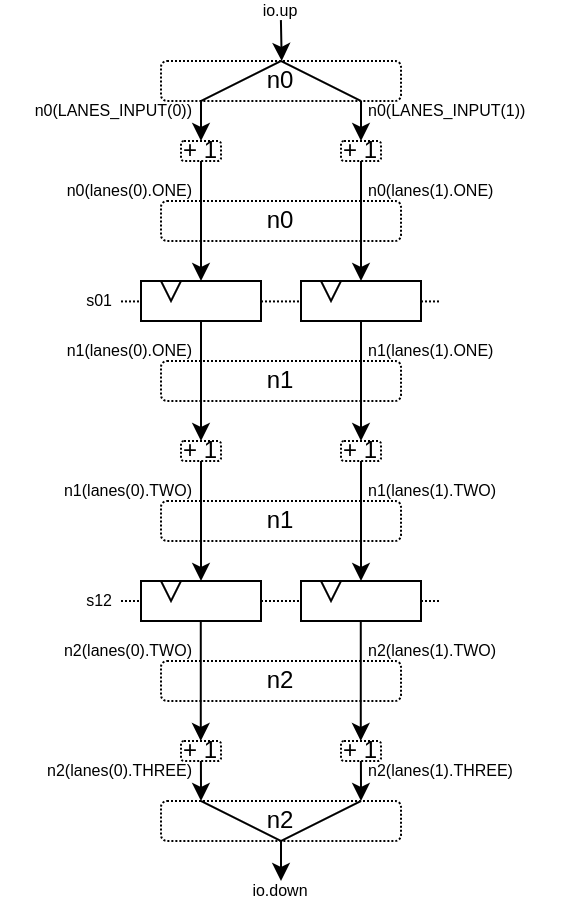
试想一下,如果您需要对 4 对数字进行浮点乘法运算(稍后求和)。并且这 4 对数字是由一个数据流同时提供的,那么就不需要 4 条不同的流水线来进行乘法运算,而需要在同一条流水线上并行处理。
下面的示例展示了一种模式,它将多个通道组成一个流水线,来并行处理它们。
// This area allows to take a input value and do +1 +1 +1 over 3 stages.
// I know that's useless, but let's pretend that instead it does a multiplication
// between two numbers over 3 stages (for FMax reasons).
class Plus3(INPUT: Payload[UInt], stage1: Node, stage2: Node, stage3: Node) extends Area {
  val ONE = stage1.insert(stage1(INPUT) + 1)
  val TWO = stage2.insert(stage2(ONE) + 1)
  val THREE = stage3.insert(stage3(TWO) + 1)
}

// Let's define a component which takes a stream as input,
// which carries 'lanesCount' values that we want to process in parallel
// and put the result on an output stream.
class TopLevel(lanesCount : Int) extends Component {
  val io = new Bundle {
    val up = slave Stream(Vec.fill(lanesCount)(UInt(16 bits)))
    val down = master Stream(Vec.fill(lanesCount)(UInt(16 bits)))
  }

  // Let's define 3 Nodes for our pipeline
  val n0, n1, n2 = Node()

  // Let's connect those nodes by using simples registers
  val s01 = StageLink(n0, n1)
  val s12 = StageLink(n1, n2)

  // Let's bind io.up to n0
  n0.arbitrateFrom(io.up)
  val LANES_INPUT = io.up.payload.map(n0.insert(_))

  // Let's use our "reusable" Plus3 area to generate each processing lane
  val lanes = for(i <- 0 until lanesCount) yield new Plus3(LANES_INPUT(i), n0, n1, n2)

  // Let's bind n2 to io.down
  n2.arbitrateTo(io.down)
  for(i <- 0 until lanesCount) io.down.payload(i) := n2(lanes(i).THREE)

  // Let's ask the builder to generate all the required hardware
  Builder(s01, s12)
}
这将产生以下数据路径(假设 lanesCount = 2 ),这里没有给出仲裁:
重定时/可变长度
有时,你想设计一个流水线,但你并不真正知道关键路径在哪里,也不知道各阶段之间如何平衡。而且通常情况下,你无法依赖综合工具做好自动重定时工作。
因此,你需要一种简单的方法来构建流水线逻辑。
下面介绍如何使用此流水线 API:
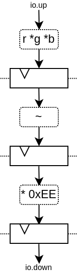
// Define a component which will take a input stream of RGB value
// Process (~(R + G + B)) * 0xEE
// And provide that result into an output stream.
class RgbToSomething(addAt : Int,
                     invAt : Int,
                     mulAt : Int,
                     resultAt : Int) extends Component {

  val io = new Bundle {
    val up = slave Stream(spinal.lib.graphic.Rgb(8, 8, 8))
    val down = master Stream (UInt(16 bits))
  }

  // Let's define the Nodes for our pipeline.
  val nodes = Array.fill(resultAt+1)(Node())

  // Let's specify which node will be used for what part of the pipeline.
  val insertNode = nodes(0)
  val addNode = nodes(addAt)
  val invNode = nodes(invAt)
  val mulNode = nodes(mulAt)
  val resultNode = nodes(resultAt)

  // Define the hardware which will feed the io.up stream into the pipeline.
  val inserter = new insertNode.Area {
    arbitrateFrom(io.up)
    val RGB = insert(io.up.payload)
  }

  // Sum the r g b values of the color.
  val adder = new addNode.Area {
    val SUM = insert(inserter.RGB.r + inserter.RGB.g + inserter.RGB.b)
  }

  // Flip all the bit of the RGB sum.
  val inverter = new invNode.Area {
    val INV = insert(~adder.SUM)
  }

  // Multiply the inverted bits with 0xEE.
  val multiplier = new mulNode.Area {
    val MUL = insert(inverter.INV*0xEE)
  }

  // Connect the end of the pipeline to the io.down stream.
  val resulter = new resultNode.Area {
    arbitrateTo(io.down)
    io.down.payload := multiplier.MUL
  }

  // Let's connect those nodes sequentially by using simples registers.
  val links = for (i <- 0 to resultAt - 1) yield StageLink(nodes(i), nodes(i + 1))

  // Let's ask the builder to generate all the required hardware
  Builder(links)
}
如果像这样生成该组件:
SpinalVerilog(
  new RgbToSomething(
    addAt    = 0,
    invAt    = 1,
    mulAt    = 2,
    resultAt = 3
  )
)
您将获得由 3 层寄存器(flip-flops)分隔的 4 个处理阶段:
请注意,生成的硬件 verilog 还算干净(至少按我的标准来说是这样 :P):
// Generator : SpinalHDL dev    git head : 1259510dd72697a4f2c388ad22b269d4d2600df7
// Component : RgbToSomething
// Git hash  : 63da021a1cd082d22124888dd6c1e5017d4a37b2

`timescale 1ns/1ps

module RgbToSomething (
  input  wire          io_up_valid,
  output wire          io_up_ready,
  input  wire [7:0]    io_up_payload_r,
  input  wire [7:0]    io_up_payload_g,
  input  wire [7:0]    io_up_payload_b,
  output wire          io_down_valid,
  input  wire          io_down_ready,
  output wire [15:0]   io_down_payload,
  input  wire          clk,
  input  wire          reset
);

  wire       [7:0]    _zz_nodes_0_adder_SUM;
  reg        [15:0]   nodes_3_multiplier_MUL;
  wire       [15:0]   nodes_2_multiplier_MUL;
  reg        [7:0]    nodes_2_inverter_INV;
  wire       [7:0]    nodes_1_inverter_INV;
  reg        [7:0]    nodes_1_adder_SUM;
  wire       [7:0]    nodes_0_adder_SUM;
  wire       [7:0]    nodes_0_inserter_RGB_r;
  wire       [7:0]    nodes_0_inserter_RGB_g;
  wire       [7:0]    nodes_0_inserter_RGB_b;
  wire                nodes_0_valid;
  reg                 nodes_0_ready;
  reg                 nodes_1_valid;
  reg                 nodes_1_ready;
  reg                 nodes_2_valid;
  reg                 nodes_2_ready;
  reg                 nodes_3_valid;
  wire                nodes_3_ready;
  wire                when_StageLink_l56;
  wire                when_StageLink_l56_1;
  wire                when_StageLink_l56_2;

  assign _zz_nodes_0_adder_SUM = (nodes_0_inserter_RGB_r + nodes_0_inserter_RGB_g);
  assign nodes_0_valid = io_up_valid;
  assign io_up_ready = nodes_0_ready;
  assign nodes_0_inserter_RGB_r = io_up_payload_r;
  assign nodes_0_inserter_RGB_g = io_up_payload_g;
  assign nodes_0_inserter_RGB_b = io_up_payload_b;
  assign nodes_0_adder_SUM = (_zz_nodes_0_adder_SUM + nodes_0_inserter_RGB_b);
  assign nodes_1_inverter_INV = (~ nodes_1_adder_SUM);
  assign nodes_2_multiplier_MUL = (nodes_2_inverter_INV * 8'hee);
  assign io_down_valid = nodes_3_valid;
  assign nodes_3_ready = io_down_ready;
  assign io_down_payload = nodes_3_multiplier_MUL;
  always @(*) begin
    nodes_0_ready = nodes_1_ready;
    if(when_StageLink_l56) begin
      nodes_0_ready = 1'b1;
    end
  end

  assign when_StageLink_l56 = (! nodes_1_valid);
  always @(*) begin
    nodes_1_ready = nodes_2_ready;
    if(when_StageLink_l56_1) begin
      nodes_1_ready = 1'b1;
    end
  end

  assign when_StageLink_l56_1 = (! nodes_2_valid);
  always @(*) begin
    nodes_2_ready = nodes_3_ready;
    if(when_StageLink_l56_2) begin
      nodes_2_ready = 1'b1;
    end
  end

  assign when_StageLink_l56_2 = (! nodes_3_valid);
  always @(posedge clk or posedge reset) begin
    if(reset) begin
      nodes_1_valid <= 1'b0;
      nodes_2_valid <= 1'b0;
      nodes_3_valid <= 1'b0;
    end else begin
      if(nodes_0_ready) begin
        nodes_1_valid <= nodes_0_valid;
      end
      if(nodes_1_ready) begin
        nodes_2_valid <= nodes_1_valid;
      end
      if(nodes_2_ready) begin
        nodes_3_valid <= nodes_2_valid;
      end
    end
  end

  always @(posedge clk) begin
    if(nodes_0_ready) begin
      nodes_1_adder_SUM <= nodes_0_adder_SUM;
    end
    if(nodes_1_ready) begin
      nodes_2_inverter_INV <= nodes_1_inverter_INV;
    end
    if(nodes_2_ready) begin
      nodes_3_multiplier_MUL <= nodes_2_multiplier_MUL;
    end
  end


endmodule
此外,您还可以轻松调整处理的级数和位置,例如,您可能希望将翻转的硬件逻辑移到与加法器相同级上。具体方法如下:
SpinalVerilog(
  new RgbToSomething(
    addAt    = 0,
    invAt    = 0,
    mulAt    = 1,
    resultAt = 2
  )
)
那么您可能需要移除输出寄存器级:
SpinalVerilog(
  new RgbToSomething(
    addAt    = 0,
    invAt    = 0,
    mulAt    = 1,
    resultAt = 1
  )
)
这个示例的一个特点是,中间值必须是 addNode 。例如:
val addNode = nodes(addAt)
// sum the r g b values of the color
val adder = new addNode.Area {
  ...
}
遗憾的是,scala 不允许用 new nodes(addAt).Area 替换 new addNode.Area。一种变通方法是将其定义为一个类,比如:
class NodeArea(at : Int) extends NodeMirror(nodes(at))
val adder = new NodeArea(addAt) {
    ...
}
根据您的管道规模,它可以带来一些好处。
简单的CPU示例
下面是一个简单的 8 位 CPU 示例:
三级流水线(fetch, decode, execute)
嵌入的获取存储器
add / jump / led /delay 指令
class Cpu extends Component {
  val fetch, decode, execute = CtrlLink()
  val f2d = StageLink(fetch.down, decode.up)
  val d2e = StageLink(decode.down, execute.up)

  val PC = Payload(UInt(8 bits))
  val INSTRUCTION = Payload(Bits(16 bits))

  val led = out(Reg(Bits(8 bits))) init(0)

  val fetcher = new fetch.Area {
    val pcReg = Reg(PC) init (0)
    up(PC) := pcReg
    up.valid := True
    when(up.isFiring) {
      pcReg := PC + 1
    }

    val mem = Mem.fill(256)(INSTRUCTION).simPublic
    INSTRUCTION := mem.readAsync(PC)
  }

  val decoder = new decode.Area {
    val opcode = INSTRUCTION(7 downto 0)
    val IS_ADD   = insert(opcode === 0x1)
    val IS_JUMP  = insert(opcode === 0x2)
    val IS_LED   = insert(opcode === 0x3)
    val IS_DELAY = insert(opcode === 0x4)
  }


  val alu = new execute.Area {
    val regfile = Reg(UInt(8 bits)) init(0)

    val flush = False
    for (stage <- List(fetch, decode)) {
      stage.throwWhen(flush, usingReady = true)
    }

    val delayCounter = Reg(UInt(8 bits)) init (0)

    when(isValid) {
      when(decoder.IS_ADD) {
        regfile := regfile + U(INSTRUCTION(15 downto 8))
      }
      when(decoder.IS_JUMP) {
        flush := True
        fetcher.pcReg := U(INSTRUCTION(15 downto 8))
      }
      when(decoder.IS_LED) {
        led := B(regfile)
      }
      when(decoder.IS_DELAY) {
        delayCounter := delayCounter + 1
        when(delayCounter === U(INSTRUCTION(15 downto 8))) {
          delayCounter := 0
        } otherwise {
          execute.haltIt()
        }
      }
    }
  }

  Builder(fetch, decode, execute, f2d, d2e)
}
下面是一个简单的测试平台,它实现了一个循环,使 led 计数值上升。
SimConfig.withFstWave.compile(new Cpu).doSim(seed = 2){ dut =>
  def nop() = BigInt(0)
  def add(value: Int) = BigInt(1 | (value << 8))
  def jump(target: Int) = BigInt(2 | (target << 8))
  def led() = BigInt(3)
  def delay(cycles: Int) = BigInt(4 | (cycles << 8))
  val mem = dut.fetcher.mem
  mem.setBigInt(0, nop())
  mem.setBigInt(1, nop())
  mem.setBigInt(2, add(0x1))
  mem.setBigInt(3, led())
  mem.setBigInt(4, delay(16))
  mem.setBigInt(5, jump(0x2))

  dut.clockDomain.forkStimulus(10)
  dut.clockDomain.waitSampling(100)
}
Note
构建流水线时,只有 node(0).valid 或 node(n).ready (其中 n 是流水线中的最后一级)可能由用户逻辑驱动。如果 node.ready 或 node.valid 信号未使用,构建器可能会优化掉它们。为了保证 node.ready 或 node.valid 信号的创建(如果您使用 CtrlLink() 或任何其他您想要流量控制的链接,这一点很重要),必须手动驱动 node(0).valid
n0.valid := io.up.valid
// or
n0.valid := True/False

//Example with CtrlLink()
case class inputStage(stage: CtrlLink) extends Area {
   stage.up.valid := True
}
这足以确保 halting 和 CtrlLink 行为按预期工作(node.valid 或 node.ready 信号不会被优化掉)。